GPSDO with Pico
GPSDO with Pico
Note
This work is mainly done by Phil Harman (VK6PH). Appreciate him granting us the permission to release this work to public
This explains the components the GPSDO uses and how the software operates. Both RX-888 and Web-888 can input an external clock as reference clock.
- [Revision 2025-04-27] Add optional battery to retain GPS RAM, so fasten the procedure of searching satellites.
Features
- User Experience: Simple and ease of use UI with a small LCD screen and an encoder.
- TCXO Output: A stable reference clock available as either a square wave or a sine wave.
- Si5351 Output: Generated by the Si5351 clock generator. The Si5351 frequency can be set anywhere from 8 kHz to 160 MHz in 1 Hz increments.
Hardware Construction Manual
OCXO
I tried several different OCXO but the OSC5A2BO2 was the best.
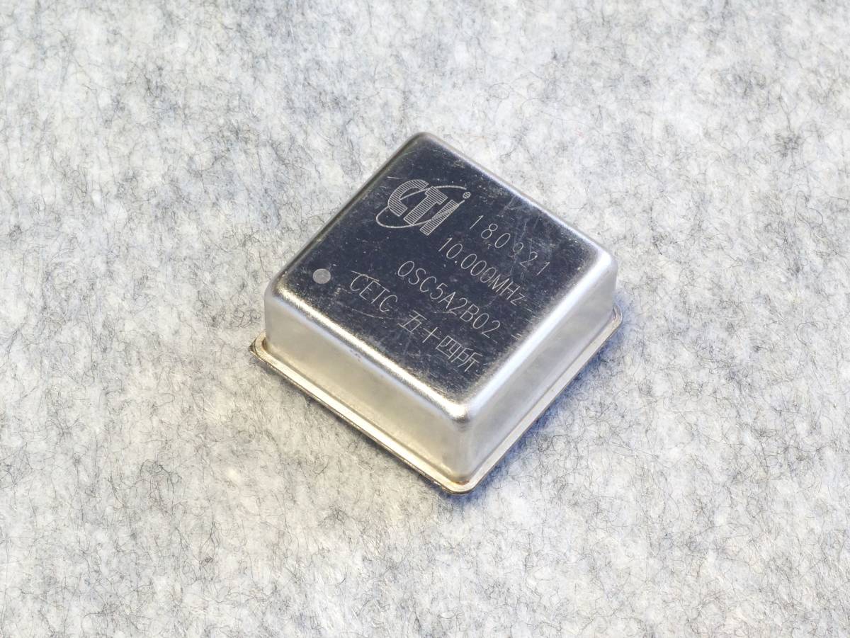
This runs from 5v, provides a 4v square wave output and requires 2v +/- 2v for the control voltage (Vc).
I cooled the OCXO to 5 degrees C and it drew 400 mA when stating and dropped to 180 mA once internally reached the required temperature.
There are many of these available on the Internet. However, they are second hand and I expect removed from say a mobile phone system. Still if they have been running for a while then their frequency would have aged.
I purchased a few from the internet and this is where I purchased:
The price is about 1/10 of a brand new one (as 12/11/2024).
GPS
I used the uBox NEO-7M GPS module.
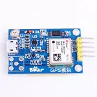
Purchased from eBay
This has more features than required e.g. antenna and USB interface. I needed the USB connection so I could experiment with the required software settings.
Now this has been determined then a simpler version, without antenna and USB, could be used. The internal antenna does not work well and may only connect to a few satellites and takes a long time to connect so an external antenna is better.
This is a simpler and lower cost version: 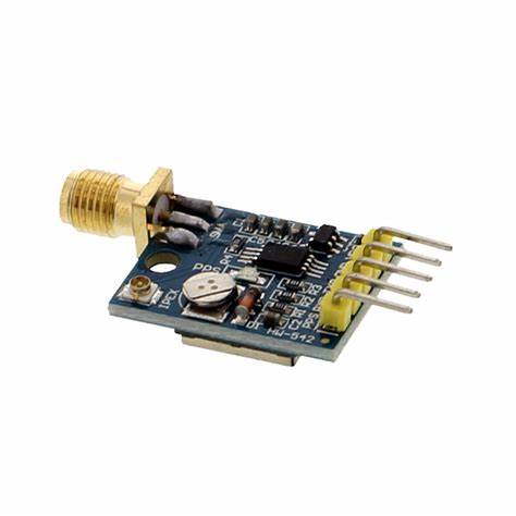
A simpler version must have 5 pins so the PPS pin is included.
Processor
I started using a Raspberry Pi Pico micro. This worked fine, has dual CPUs and 8 PIO’s. The code is written in C++ using the Arduino IDE and public libraries.
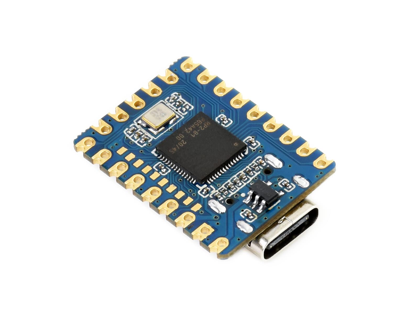
I later found the Pico Zero, which is much smaller and lower cost. This is what it looks like:
OLED
I use a 1.54 inch, I2C, SSD1309. I did try a 0.96 inch SSD1306 but its just a little small to read the information on the screen.
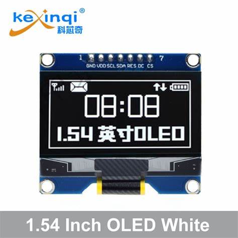
Prices seem low on AliExpress.
XOR chip
This is an SN74HC86, one of the 4 XOR gates is used in the PLL and the other 3 for providing the 10 MHz output. I get from lcsc.com – C4472516.
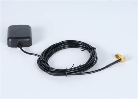
Antenna
An external antenna works well. A car GPS antenna with SMA connector and 2 m of cable is fine and low price on AliExpress.
Software Operation Manual
When starting the NEO-7M needs to be set up to be in stationary mode, since better accuracy, and just the data output we require. This takes about a second and the screen shows this taking place.
Basic UI Instructions
Setting up started
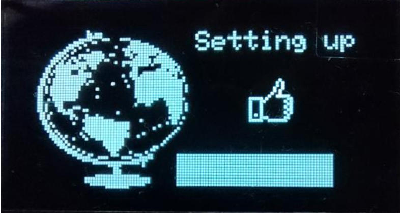
Setting up completed

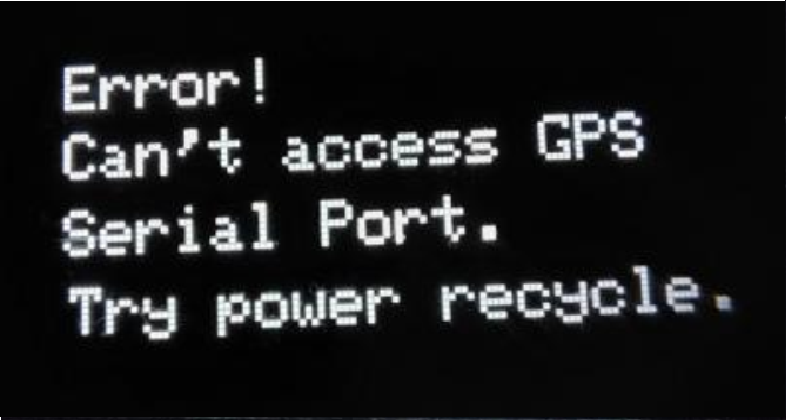
If there is a problem setting up then a message is shown.
Then it starts looking for satellites and displays how many have been found.
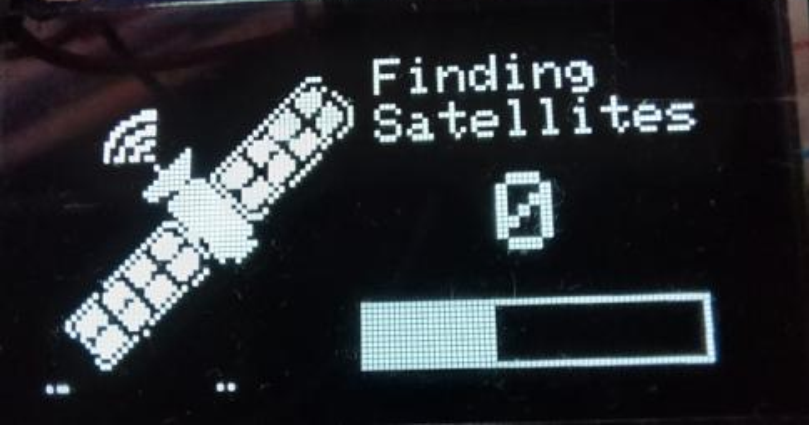
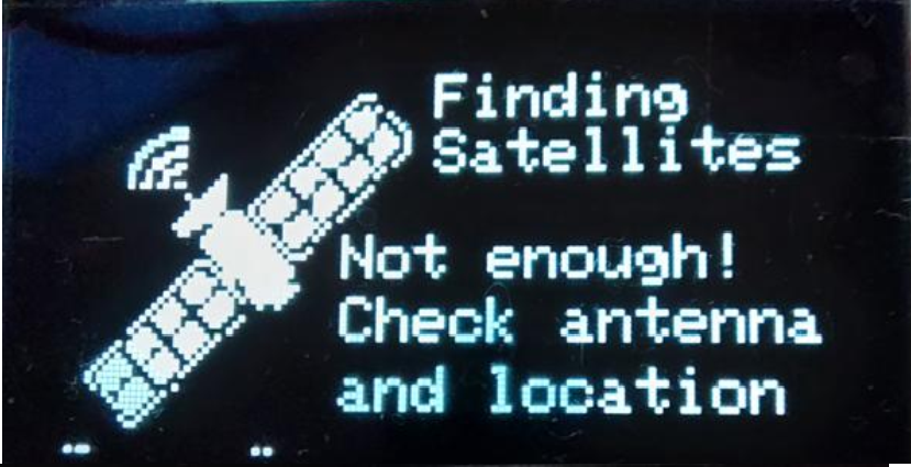
The bar graph allows 2 minutes. We need 3 satellites for the PLL to work so if after 2 minutes there is not enough this message is shown It will stay in this loop until 3 satellites are found.
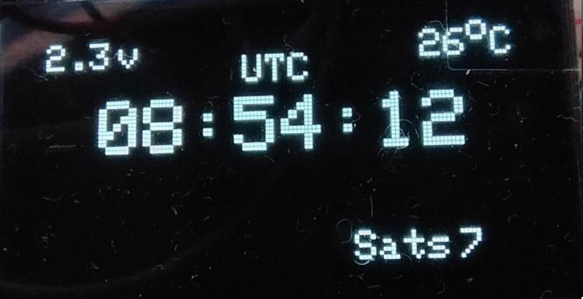
Once 3 satellites have been found then the main screen is shown.
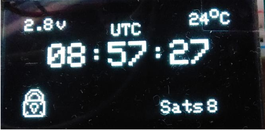
This shows the current UTC time, updated every second, the number of satellites found, the temperature of the Pico Zero and the PLL control voltage. It then waits for the PLL to lock and when locked shows a lock symbol.
It then stays in this mode and if the PLL should unlock for some reason then an X is placed over the lock symbol.
Setting the Si5351 Frequency
- Enter Setup Mode:
- Press and hold the knob button for more than one second to enter the Si5351 setup screen.
- Adjust Frequency:
Turn the knob to adjust the highlighted digit.
Press the knob briefly (less than one second) to move the underline to a different digit.
- Save and Exit:
Once the desired frequency is set, press and hold the knob button for more than one second. The selected frequency will:
Be displayed on the main screen,
Be saved to EEPROM,
And be retained even after the device is powered off.
Schematic, Gerber file, BOM and Software
I’ve attached a copy of the schematic that I suggest be used. The 5v supply for the OCXO comes from the USB C port. The takes about 500 mA when starting from cold and using my PC to power it, and read from the USB port, works fine. The GPSDO can also be powered from a 5v plug pack since a USB connection is not required.
The OCXO provides a 4v square wave output that is connected to the Pico Zero. I have confirmed that a Pico Zero can take up to 5v at a GPIO.
Tips
How to use Gerber file to order PCB from JLC, please refer the document here: Instruction