RF Upconverter
RF Upconverter
An RF upconverter is a device used to raise low-frequency signals to higher frequencies for transmission or processing. A key component in this process is the RF mixer, which combines an input signal with a local oscillator (LO) frequency to produce a new output frequency.
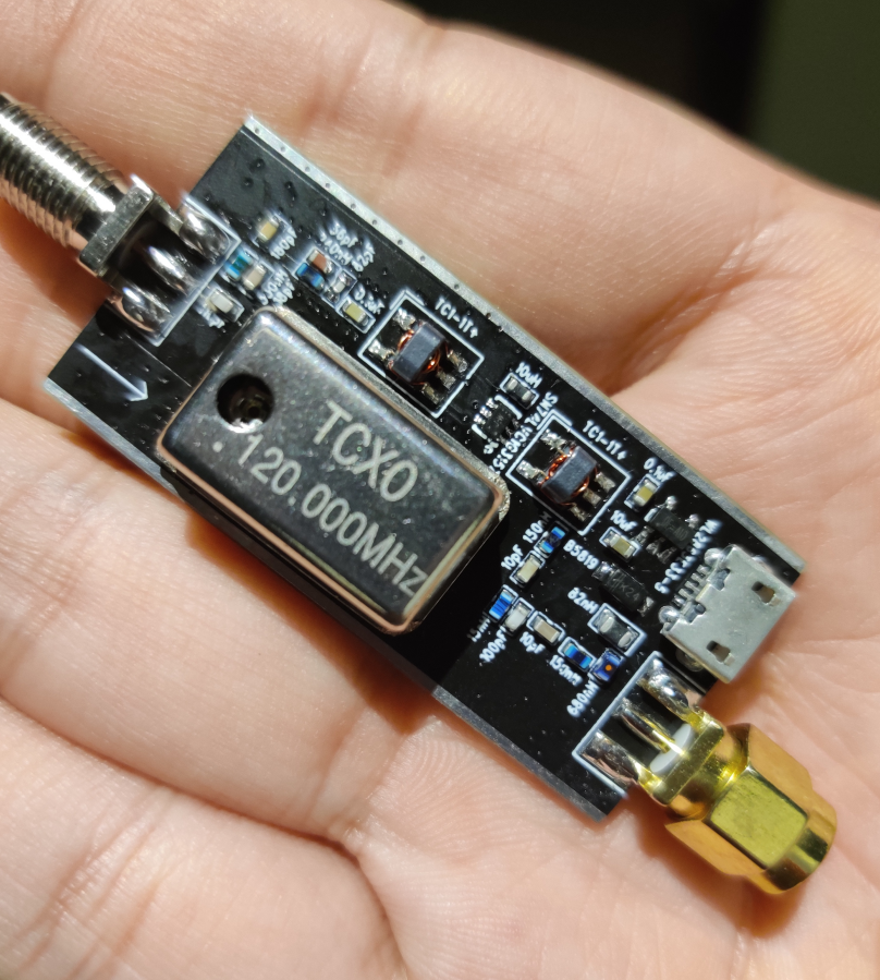
This design targets upconverting a 10 kHz to 30 MHz signal to a 120 MHz - 150 MHz range (tunable by changing the crystal, typically 120 MHz to 125 MHz). It utilizes two analog switches (TI SN74LVC1G3157) to form the Tayloe mixer. The board is powered by USB 5V and employs 0603 components, resulting in a compact design.

The 2T H-mode mixer, an advanced mixer design, utilizes two analog switches, achieving low noise, excellent linearity, and robust suppression of LO feedthrough. This design leverages high LO drive levels for superior dynamic range and avoids active biasing for optimal signal purity. The resulting clarity and stability make it a preferred option for sensitive high-performance RF applications, enhancing signal integrity and reducing unwanted noise.
Signal Path
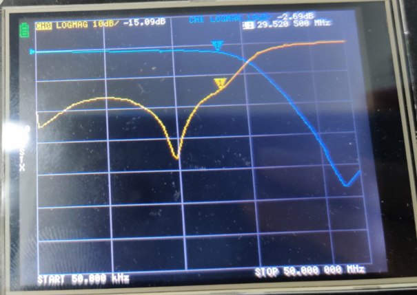
- The input signal first passes through a 30 MHz low-pass filter (LPF).

The filtered signal enters T1, converting it to differential signals.
Two switches configured as a Tayloe mixer are used to mix the signal with the local oscillator (LO).
The signal is then converted back to a single-ended signal.
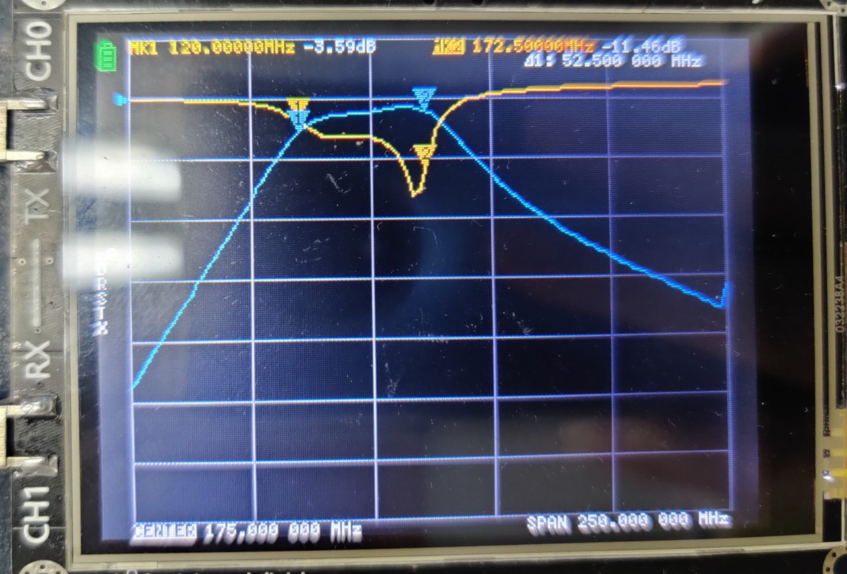
Finally, the signal passes through a band-pass filter (BPF) to remove unwanted aliasing.

Bill of Materials
| ID | Quantity | Name | Package | Description |
|---|---|---|---|---|
| 1 | 1 | C26 | R0603 | 0.1µF |
| 2 | 1 | C29 | C0603 | 0.1µF |
| 3 | 1 | C7 | R0603 | 100nF |
| 4 | 1 | C72 | C0603 | 10µF |
| 5 | 1 | C2 | R0603 | 110pF |
| 6 | 3 | C1 C3 C64 | R0603 | 12pF |
| 7 | 3 | C5 C22 C49 | R0603 | 15pF |
| 8 | 1 | C19 | C0603 | 22pF |
| 9 | 1 | C6 | C0402 | 4.7µF |
| 10 | 1 | C31 | C0603 | 4.7µF |
| 11 | 1 | C16 | R0603 | 50pF |
| 12 | 1 | C20 | R0603 | 5pF |
| 13 | 1 | C18 | C0603 | 82pF |
| 14 | 1 | C37 | C0603 | 10µF |
| 15 | 1 | CY1 | 7050_CRYSTAL-A | 125MHz |
| 16 | 1 | CY2 | DIP-14-DIP | 125MHz |
| 17 | 2 | D1 D2108 | SOD323 | B5819WS |
| 18 | 1 | LA3 | R0805 | 600R-100M |
| 19 | 2 | L3 L15 | R0603 | 100nH |
| 20 | 1 | L12 | R0805-R | 10µH |
| 21 | 1 | L7 | R0603 | 180nH |
| 22 | 3 | L1-2 L6 | R0603 | 22nH |
| 23 | 1 | L5 | R0805 | 22nH |
| 24 | 1 | L16 | R0603 | 27nH |
| 25 | 1 | L10 | R0603 | 82nH |
| 26 | 1 | LED3 | LED-0603 | LED |
| 27 | 1 | U21 | SOT23-5 | WL2863E33-5/TR |
| 28 | 1 | RA1 | R0603 | 0R |
| 29 | 3 | RA2-3 RA6 | R0603 | 10K |
| 30 | 2 | RA7-8 | R0603 | 2.8R |
| 31 | 1 | RA5 | R0603 | 430R |
| 32 | 1 | RA4 | R0603 | 4.7K |
| 33 | 2 | U1-2 | SMA-L | SMA Connectors |
| 34 | 2 | U14 U20 | SC70-6 | SN74LVC1G3157 |
| 35 | 2 | T1-2 | AT1521 | Transformers |
| 36 | 1 | J2500 | USB20MICRO5_MU05_10MGF_T | USB20_micro |
Schematics and PCB Design
Gerber Files
Tips
For instructions on how to use Gerber files to order PCBs from JLCPCB, please refer to the document here: Instruction