Configuration Tab
Configuration Tab
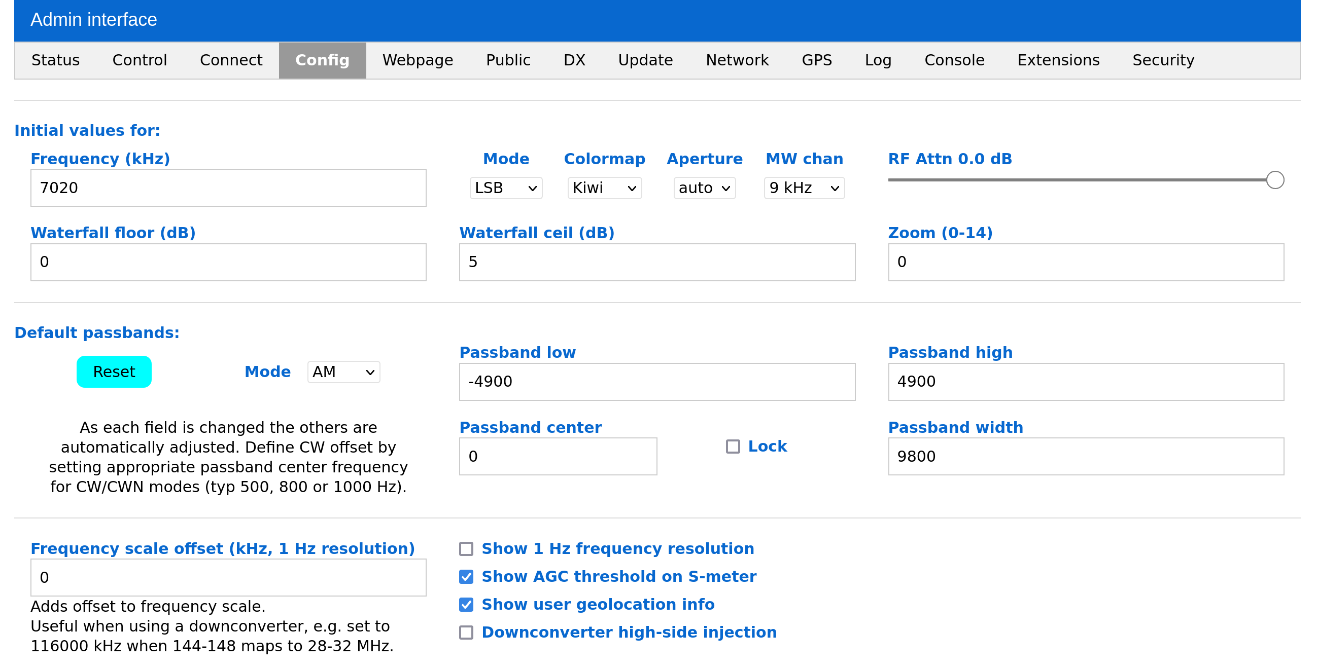
Switching to the Config tab allows you to modify initialization parameters according to your local conditions. These parameters also determine the default settings that the Web-888 SDR presents to users when they establish a new connection.
Basic User Settings
For normal users, the following values can be changed:
- Frequency (kHz): Initial frequency setting
- Mode: Broadcast mode (AM, SSB, CW, etc.)
- Colormap: Color scheme of the spectrum display (set according to your preference)
- Max receiver frequency: The frequency range received by the Web-888 SDR (up to 62 MHz)
- ITU region: ITU region (based on your country)
- Initial AM BCB channel spacing: Medium wave step unit (9 kHz, 10 kHz)
Status LED Brightness
Adjust the brightness of the status LED to your preference.
CAT Interface Baud Rate
If you connect a USB serial adapter for CAT control, this setting enables the UART interface to report frequency tuning information. The default setting is disabled.
RF Attenuator Access Control
This setting controls who can change the attenuator settings in the user interface. By default, only local connections are allowed to make these changes.
External Reference Clock
Enable this option when you want to use an external 10 MHz reference clock input from the EXT-CLK port. By default, this feature is disabled, and the Web-888 uses its internal TCXO at 24.768 MHz as the reference clock.
External Clock Output Frequency
Enter a frequency value (in Hz) to configure the Web-888 to output a clock signal at that frequency from the EXT-CLK port. By default, this value is 0, which means this feature is disabled.
Warning
The external reference clock and external clock output features cannot be used simultaneously as they both utilize the EXT-CLK port.
GPS Correction of ADC Clock
This setting controls how frequently the PPS (Pulse Per Second) signal is used to calibrate the ADC clock frequency. This only changes the DSP parameters related to the ADC clock rate and does not physically alter the clock frequency like the "Correct ADC Clock by GPS PPS" feature does. By default, this is set to "continuous." For long-period signals like WSPR and FST4W, you may need to change this setting to a much slower frequency.
ADC Dither
ADC dithering is a technique where controlled noise is intentionally added to the input signal before digitization. While this might seem counterintuitive, it actually helps improve the performance of the ADC by reducing quantization errors and distortion.
Key benefits of ADC dithering:
- Improved Quantization: By adding noise, dithering breaks the correlation between quantization error and the input signal, resulting in a more accurate digital representation.
- Enhanced Linearity: It helps randomize differential non-linearity (DNL) errors, improving the overall linearity of the ADC.
- Increased Resolution: For slowly varying signals, dithering can effectively increase resolution through averaging.
In essence, dithering helps achieve a more precise and higher-quality digital signal by mitigating the limitations of the ADC's quantization process.
Default setting: OFF, as enabling this feature will increase the noise floor.
ADC PGA
An ADC PGA (Analog-to-Digital Converter with Programmable Gain Amplifier) combines an analog-to-digital converter (ADC) and a programmable gain amplifier (PGA). The PGA amplifies low-level signals before they are digitized by the ADC, enhancing the dynamic range and accuracy of measurements.
Key benefits of an ADC with PGA:
- Increased Dynamic Range: The PGA amplifies weak signals, allowing the ADC to better distinguish small changes in the signal.
- Flexibility: The programmable gain amplifier allows for different levels of amplification based on the application's needs.
- Improved Accuracy: Amplifying the signal before digitization reduces the impact of noise and quantization errors.
Default setting: OFF, as enabling this feature will increase the noise floor.
Correct ADC Clock by GPS PPS
Enabling this option uses the PPS signal from the GPS to correct the ADC clock by tuning the Si5351. This ensures the ADC clock is very close to the desired frequency. However, it will introduce some jitter to the clock, which can impact ADC performance. The default setting is OFF.